First and foremost, I need to stress that you need to avoid all electrical connectors if you do this install with the battery connected. If you have any doubts, disconnect the battery; that way you will be sure to end up with all of your air bags intact.
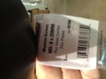
Next, hie yourself down to the local Home Depot or Lowe's and buy two packages of three metric machine screws, size M5-.8 x 20 mm, with pan heads:
![Image]()
The screws that Toyota's parts supplier used on this accessory are soft and very easily stripped. I had the torque limiter on low on my electric screwgun, and I stripped out a head in less than a second. The US sourced screws will not do you wrong.
Second, get ready to place yourself in some very uncomfortable positions. Much of this work involves squatting half in and half out of the car, bending around the front seats. Not pleasant, particularly in the wintertime.
The console is apparently a part for the Toyota Yaris. It is a drop in fit into the iQ excepting only the streamlined fairing fitted under the actual arm rest box. I have installed it "as is" for now, but I plan to contour the front of the fairing so as to eliminate the cutout for the brake handle, while still covering the metal protrusions at the front of the mounting bracket.
While I sourced my arm rest from Nippon, you might want to check out the cost with your local Toyota dealer. If nothing else, you will save on shipping.
Installation was relatively trouble free, save only the screws. I cannot stress it enough - get your own screws from the local hardware.
Installation started by carefully removing the bolts (2) holding the inner seat rail for each front seat. They don't look like hex heads, but an 8 mm socket will remove and install them without damage.
Once the bolts are removed, take the two small metal brackets (marked L and R) and place them beneath the seat rails, hooking the hook shaped edge over the outside of the seat rail. Once hooked in place, slide them all the way to the rear until their square ends butt up against the plastic piece at the end of the rail.
I don't have a good photo of this, for reasons that will become apparent later in this narrative, but you can just see the one bracket in the photograph below.
![Image]()
In this photo, the small bracket is located beneath the seat rail, and is butted all the way to the right in the photo.
Once the small brackets are in place, reinstall and tighten the seat rail bolts. As originally installed, they were hard to break. I don't have a torque figure for these bolts; perhaps someone else can fill us in on that. Note that the holes are self aligning, as the bolts for the other seat rail have not been removed.
Next is the installation of the main bracket for the arm rest. It is oriented with the small metal tab (as seen in the photo below) pointing towards the front of the car.
At first glance, the bracket does not appear to fit. However, it is "sprung" into place when installing, and all will be fine once you are done.
Install the two machine screws through the upper bracket so that they screw into the threaded holes in one of the bottom brackets. Do this slowly and carefully, with a non-powered screw driver.
Do not tighten the screws home at this point - just have them threaded into their holes so that they hold the one side of the bracket in alignment with the lower bracket.
Once one side of the support bracket has been installed, "spring" it over so that the holes in its bottom portion are aligned with the threaded holes in the lower bracket on that side. Carefully install two screws into their holes on this side. Then, manually screw down the four screws a little bit at a time until the upper bracket is snug against the two lower brackets.
Here is a photo of the bracket installed in place, with all four screws made up tight:
![Image]()
This is a view of the installed bracket from the top; note the silver screw on the one side, and the stripped out screw head to the rear of it. When I find my screw extractors, I'll be pulling it and installing another shiny screw, as seen on the left…when I find my screw extractors…
Follow this with a break, as the worst of the work is done.
Take a length of black door edge trim (the smaller size) and cut off four 5 ½" pieces, with square ends:
![Image]()
These are needed to protect the four long exposed edges of the support bracket should you wish to utilize the space beneath the arm rest for additional storage. The metal as shipped has sharp edges, and this protection is needed to keep your hands uninjured when accessing this space. Do not install them at this time, however.
Dry fit the streamlined fairing over the top of the support bracket. It does not lie well, but will self align once the arm rest box is in place. Place the arm rest box atop the bracket, with the cup holder portion to the rear. Open the storage compartment door, and carefully install the four screws provided through the bottom of the box and into the bracket. Drop in the small piece of carpet, black side up, and there's your installed arm rest, shown upside down in this photo
:
![Image]()
Now, to protect your arms and hands against injury, slip one of the 5 ½" long pieces of black trim onto each of the exposed front and back edges of the support bracket. The black trim blends in well with the color of the support, and the thick glue inside of the trim will keep it firmly in place. Tap the trim into place to ensure a good bond between the glue and the support.
Other than the shaping of the front edge of the fairing to remove the cutout shaped area for the hand brake on the Yaris, you are done. However, pay close attention to how the rear seat backs fit against the arm rest when the seats are folded down and the cup holder is deployed.
![Image]()
As you can see, the seat backs ever so slightly overlap the top of the cup holder. With care, you can tuck the soft portions of the seat backs around the cup holder, but that tends to fold it closed. (There is no problem with the seat backs up.)
Some outside of the box thinking led me to reverse the orientation of the arm rest box so the cup holder is to the front, and the storage box to the rear, just to see how it would work. The cup holder was free and clear, and (more importantly) is towards the front. However, when this is done, the cup holder hinges downward far too far. It might be possible to fix a stop to limit its motion to a level position, but I'm not the one to do it.
So, that's it (and not in a nutshell). Enjoy the extra storage space and the arm rest (for you short people). Sorry about the upside down photos; I tried rotating them and reloading them, but they still came out upside down.
Next, hie yourself down to the local Home Depot or Lowe's and buy two packages of three metric machine screws, size M5-.8 x 20 mm, with pan heads:

The screws that Toyota's parts supplier used on this accessory are soft and very easily stripped. I had the torque limiter on low on my electric screwgun, and I stripped out a head in less than a second. The US sourced screws will not do you wrong.
Second, get ready to place yourself in some very uncomfortable positions. Much of this work involves squatting half in and half out of the car, bending around the front seats. Not pleasant, particularly in the wintertime.
The console is apparently a part for the Toyota Yaris. It is a drop in fit into the iQ excepting only the streamlined fairing fitted under the actual arm rest box. I have installed it "as is" for now, but I plan to contour the front of the fairing so as to eliminate the cutout for the brake handle, while still covering the metal protrusions at the front of the mounting bracket.
While I sourced my arm rest from Nippon, you might want to check out the cost with your local Toyota dealer. If nothing else, you will save on shipping.
Installation was relatively trouble free, save only the screws. I cannot stress it enough - get your own screws from the local hardware.
Installation started by carefully removing the bolts (2) holding the inner seat rail for each front seat. They don't look like hex heads, but an 8 mm socket will remove and install them without damage.
Once the bolts are removed, take the two small metal brackets (marked L and R) and place them beneath the seat rails, hooking the hook shaped edge over the outside of the seat rail. Once hooked in place, slide them all the way to the rear until their square ends butt up against the plastic piece at the end of the rail.
I don't have a good photo of this, for reasons that will become apparent later in this narrative, but you can just see the one bracket in the photograph below.

In this photo, the small bracket is located beneath the seat rail, and is butted all the way to the right in the photo.
Once the small brackets are in place, reinstall and tighten the seat rail bolts. As originally installed, they were hard to break. I don't have a torque figure for these bolts; perhaps someone else can fill us in on that. Note that the holes are self aligning, as the bolts for the other seat rail have not been removed.
Next is the installation of the main bracket for the arm rest. It is oriented with the small metal tab (as seen in the photo below) pointing towards the front of the car.
At first glance, the bracket does not appear to fit. However, it is "sprung" into place when installing, and all will be fine once you are done.
Install the two machine screws through the upper bracket so that they screw into the threaded holes in one of the bottom brackets. Do this slowly and carefully, with a non-powered screw driver.
Do not tighten the screws home at this point - just have them threaded into their holes so that they hold the one side of the bracket in alignment with the lower bracket.
Once one side of the support bracket has been installed, "spring" it over so that the holes in its bottom portion are aligned with the threaded holes in the lower bracket on that side. Carefully install two screws into their holes on this side. Then, manually screw down the four screws a little bit at a time until the upper bracket is snug against the two lower brackets.
Here is a photo of the bracket installed in place, with all four screws made up tight:

This is a view of the installed bracket from the top; note the silver screw on the one side, and the stripped out screw head to the rear of it. When I find my screw extractors, I'll be pulling it and installing another shiny screw, as seen on the left…when I find my screw extractors…
Follow this with a break, as the worst of the work is done.
Take a length of black door edge trim (the smaller size) and cut off four 5 ½" pieces, with square ends:

These are needed to protect the four long exposed edges of the support bracket should you wish to utilize the space beneath the arm rest for additional storage. The metal as shipped has sharp edges, and this protection is needed to keep your hands uninjured when accessing this space. Do not install them at this time, however.
Dry fit the streamlined fairing over the top of the support bracket. It does not lie well, but will self align once the arm rest box is in place. Place the arm rest box atop the bracket, with the cup holder portion to the rear. Open the storage compartment door, and carefully install the four screws provided through the bottom of the box and into the bracket. Drop in the small piece of carpet, black side up, and there's your installed arm rest, shown upside down in this photo
:

Now, to protect your arms and hands against injury, slip one of the 5 ½" long pieces of black trim onto each of the exposed front and back edges of the support bracket. The black trim blends in well with the color of the support, and the thick glue inside of the trim will keep it firmly in place. Tap the trim into place to ensure a good bond between the glue and the support.
Other than the shaping of the front edge of the fairing to remove the cutout shaped area for the hand brake on the Yaris, you are done. However, pay close attention to how the rear seat backs fit against the arm rest when the seats are folded down and the cup holder is deployed.

As you can see, the seat backs ever so slightly overlap the top of the cup holder. With care, you can tuck the soft portions of the seat backs around the cup holder, but that tends to fold it closed. (There is no problem with the seat backs up.)
Some outside of the box thinking led me to reverse the orientation of the arm rest box so the cup holder is to the front, and the storage box to the rear, just to see how it would work. The cup holder was free and clear, and (more importantly) is towards the front. However, when this is done, the cup holder hinges downward far too far. It might be possible to fix a stop to limit its motion to a level position, but I'm not the one to do it.
So, that's it (and not in a nutshell). Enjoy the extra storage space and the arm rest (for you short people). Sorry about the upside down photos; I tried rotating them and reloading them, but they still came out upside down.
![photo 1[1].jpg](/d3/attachments/2/2052-9f1ecef390f51a01292d956092d28810.jpg)
![photo 2[1].jpg](/d3/attachments/2/2053-318b842e186c3ba43196edd01ce3dd99.jpg)